


| |
| |
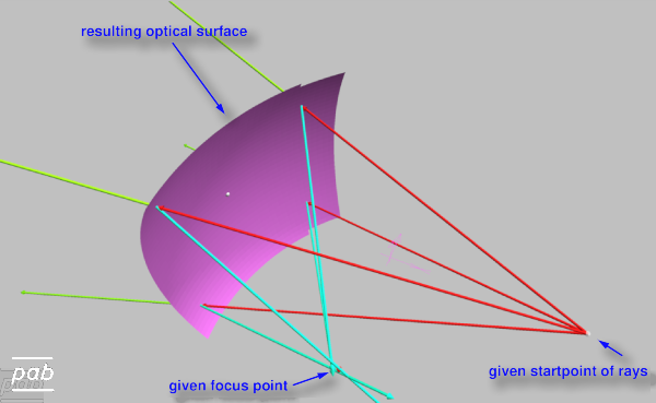
Redefining the location of the target focus point redefines the surfaces, which is build accordingly, as shown in an animation: mpeg animation of varying focus point. For this simple case, the resulting surface is an ellipsoid, as expected by the underlying mathematics. But our numerical method cares also for the general case, for which there is no explicit formula.
 | |
| |
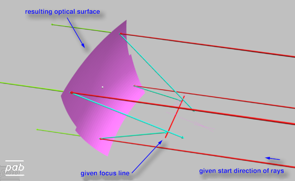
The power of this method is illustrated in this case, in which the focal area is a line segment of varying length.
When varying the length of the segment, the resulting surface adapts and the curvature is relaxed to focus all incoming light rays
on the increasing target line: mpeg animation of focus line.
Here we used a bunch of incoming parallel rays, rather than rays originating from a single point.
Note that the resulting surface is only of parabolic shape for a target point. For complex focal areas the resulting surface is
neither parabolic nor elliptical, but a true freeform surface.
The red lines show incoming light rays, blue lines represent light rays reflected by the surface and green line progate in the incoming
direction through the surface.
These rays are shown for visualization purposes and traced as a check after the surface was generated for each focus area.
Shape and material define optical features and visual appearance.
Yet freeform surfaces generated by CAD systems are very elaborated, but not constraint by physical laws.
They offer greatest flexibility to the designer, but optical properties are not ensured
during the design phase.
Traditionally, optical properties have thus to be tested in an external step, making
design cycles a trial-and-error approach, which is slow and erroneous.
Our programs generate the freeform surface directly from optical properties, thus achieving an optimal optical
solution in one run. The optimal surfaces are translated into descriptions suitable for CAD and directly usable
in the CAD system.
This method offers numerous advantages:
The method can be used for any problem in which light is to be guided to specific areas. So far it has been successfully used to generate free form surfaces for:
please contact us for details

